Digital calipers are, I confess, a guilty little pleasure of mine. After all, a vernier scale requires no batteries, and it is not all that difficult to read, now is it? And I have one with a dial indicator, also fully mechanical, which is even easier to read than a vernier. Nonetheless, the direct digital readout and the ability to zero at any point beguiled me a few decades ago, upon which I became the owner of a cheap Chinese digital caliper.
And indeed, joy reigned supreme, as anticipated.
A month later, however, it was dead. After a brief panic, it was found to be merely a flat battery, though. (A flat cell, actually, if we want to be punctilious, as we often do.) So I replaced it, and order was restored to the universe.
But of course you know where this is going. It turns out that digital calipers come in two flavours: those made by Mitutoyo, and rubbish. And of course, being stingy, I bought the latter. It is not as if I need one – I merely want it, and hence went way down-market, as is my wont in such cases. A quick search of the collective wisdom of the masses confirmed that the cheap units indeed drain their batteries/cells within weeks, or maybe a few months if you are lucky. But you never are.
OK, so you remove the cell after using it, and store it thus until the next measurement, which could be days or months later. This I did, but of course it rankles – the entire raison d’être of the digital caliper is ease of use, which is somewhat impaired by these additional steps.
There has to be a better way, and indeed many people have found it – either by hacking in an on/off switch, or by running it off an external AAA-cell, with or without a switch. This is all very well, but inelegant. With a piggy-back power supply it does not fit in its case anymore, and a switch requires some drastic internal surgery, which is against regulations. (My house, my rules.) Furthermore, and this is not to be sniffed at, chemical cells leak. All types, be their claims to the contrary as lofty as you like. Leaving one for years in a beloved toy is simply asking for it. This too is a subject I am currently rather sensitive about, and not yet ready to discuss, lest old (and new) wounds be painfully re-opened.
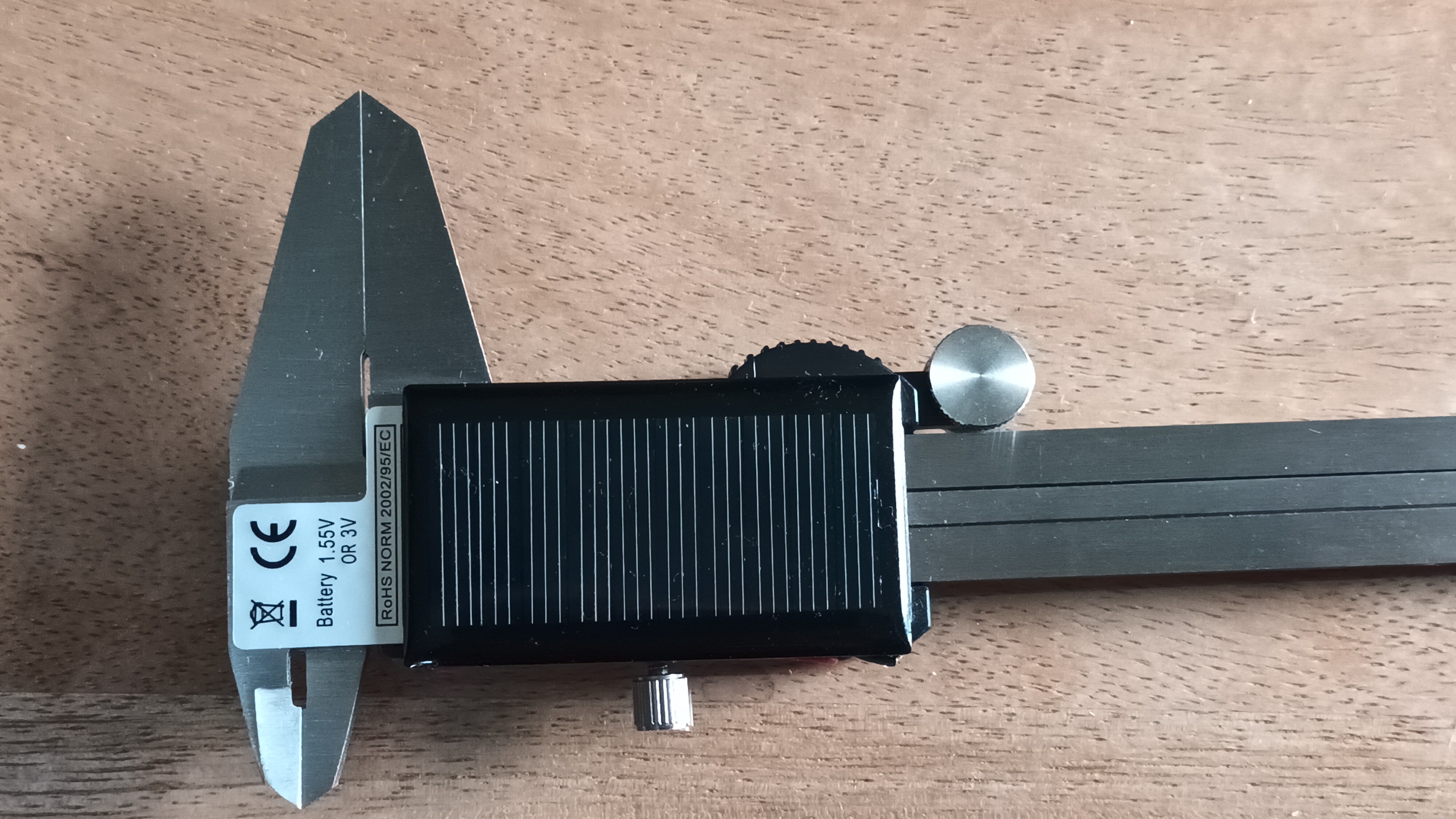
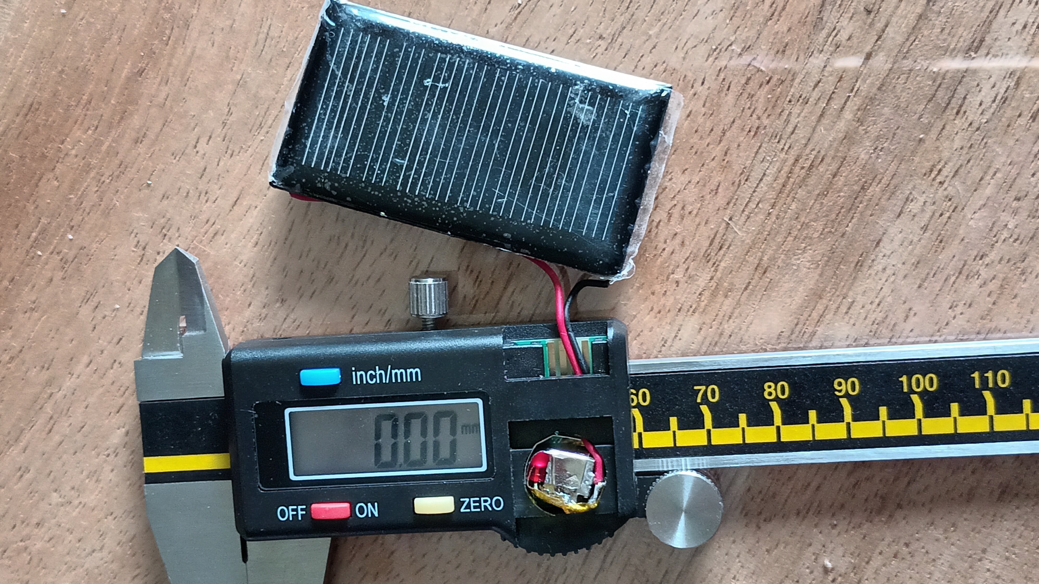
And then, while messing about on another project, I came across one of these: Polycrystalline Solar Panel 0.15W 5V. (They can be found at your favourite Eastern bazaar by the bushel, for a pittance.) At a size of 53mm x 30mm it fits beautifully on the back of the caliper - almost as if it belongs there. Even in diffuse indoor light it produces a few volts, which is good, because we probably need at least 1.4V or so for the calipers to function properly, and it is easier to regulate down than to step up. And current is not a problem - 20μA or so should be ample. But the 5V+ maximum, as produced in full sunlight, may be excessive, so we need some kind of voltage regulator. And probably an energy store, and all of this has to fit in the space vacated by the late LR44 cell. I could have used the dial caliper to measure the cell dimensions, but instead I chose to Google it: it turns out that an LR44 cell is nominally 11.6mm in diameter, and 5.4mm in thickness. Not much space to work with, forcing us to keep it simple. So here is our circuit:
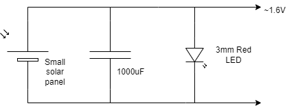
A scavenged 3mm red LED serves as a poor man’s voltage regulator. It probably works rather hard when the solar panel is exposed to direct sunlight, but a test showed it coping surprisingly well, with no noticeable ill effect. A less reckless person may have added a small resistor (maybe a few hundred ohms to perhaps one kilo-ohm) in series with the panel, but I did not feel like doing that. Rarely if ever do I desire to measure to sub-millimetre accuracy while in direct sunlight, and it turns out I can if I want to anyway. Accordingly we cast prudence to the winds and eschew the resistor. This is supposed to be a hack, after all.
So how can we fit a decent capacitor into the battery compartment? Luckily the voltage is low, so we could even use a supercapacitor - one gets them in that form factor, of course. But tests have shown that the caliper happily runs for a minute or so even on a 1000 μF capacitor charged to 1.6V as in the circuit above, and furthermore a supercap may perhaps take a while to charge up, and where is our instant gratification then, eh? We found a strip of these surprisingly svelte 100 μF SMD ceramic capacitors. The form factor is 1206, which means they are 3.6mm long and 1.6mm square, and the 6.3V maximum voltage should be ample, even if things gang agley, as even the best-laid plans aft tend to do. And they are not polarized to boot, which simplifies life.
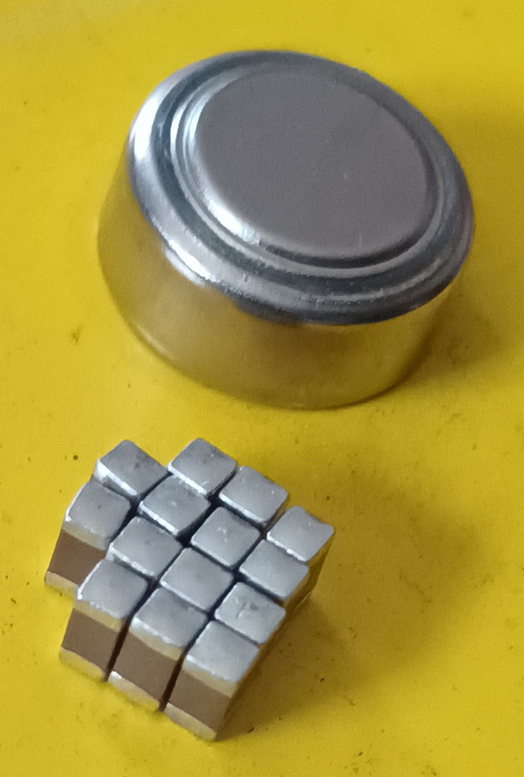
Fourteen of these 100 μF capacitors in parallel should give us enough capacitance to work with, leaving some space for the LED and the necessary isolation and contacts, while still fitting in the original volume. The goal, of course, is to refrain from physically modifying the caliper itself. (I do not know why this is so, but there you are. I only work here.)
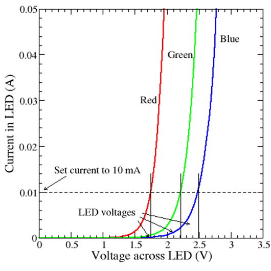
Let us talk for a moment about the LED. Why red? Well, it is mostly about the band gap – in general the shorter the wavelength, the bigger the band gap, and the higher the operating voltage. Pushing 5mA through the 3mm red LED I had on hand, the voltage settled at about 1.58V, rising to 1.65V at 20mA. Not too bad a regulator, especially when taking into account the cost (which is approximately zero, even if you had to buy it, which I did not.) An SMD LED would have been even nicer – I see one can get them in the 1206 form factor too, which would be quite cute combined with the capacitor bank we had built, but I used what was at hand. (Yes, I know one gets 1.5V Zener diodes, but none of those were lying around.) So I simply soldered everything together as shown in the circuit. Afterwards the capacitance tester reported that the capacitors had miraculously not only survived the rather brutal soldering process, but that we had indeed made a 1.5mF capacitor – we even got a small bonus, or maybe the meter was merely magnanimous.
Some Kapton tape and nickel strips, judiciously applied, turned it into a reasonable facsimile of the original LR44 cell, which could be stuffed into the compartment, pressing against the original contacts as intended. The wires to the solar panel were threaded through to the other compartment (where one can actually also access the power terminals, as well as communicate with the device, if one were so inclined. (One is, actually, but that is a project for another day.)
Total cost: hardly more than what I paid for a couple of LR44 cells the last time, because my time is simultaneously free and priceless. (And remember, it also takes time to go and buy batteries. Regularly, while cursing.) Of course we are not saving much money, or even the planet - that never was the point. It is about quality of life. I am saving aggravation, and, most importantly, the journey itself amused me, the value of which is incalculable.
And it seems to work. Time to peel the protective plastic off the panel and to close up.