Close
0%
0%

Arduino-Compatible FPGA Shield

Spartan 6 FPGA Shield includes SPI Configuration Flash, Breakout Headers, SRAM, programmable from Arduino or SPI Programmer

Similar projects worth following

Motivated by an interest in teaching folks how to use FPGAs and espouse the virtues of FPGA-coolness (& like many, frustrated a bit by a number of limitations of the Arduino incl. IO, peripherals, etc) I’ve endeavored to create the first (that I know of) FPGA-based Arduino shield.


This board - which I'm documenting here as I go along - includes heaps of additional IO, memory resources, etc. and is SPI programmable via SPI flash (including programming from the Arduino Due)...And is just an all-round cool way to introduce programmable device technology (beyond simple logic) to the uninitiated.

Likewise, it will have more than enough grunt for the old-pro to hack together some totally awesome, totally re-configurable systems.  

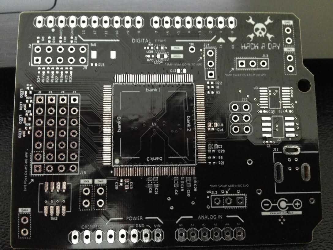
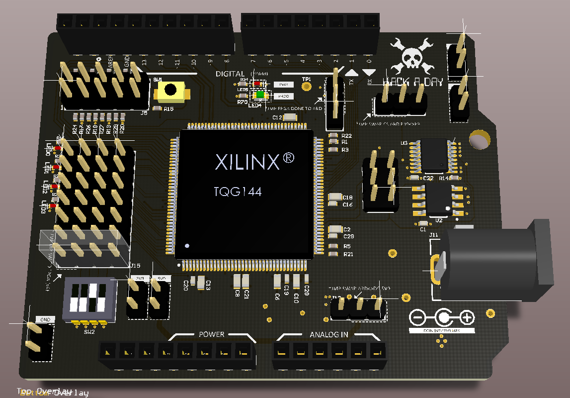
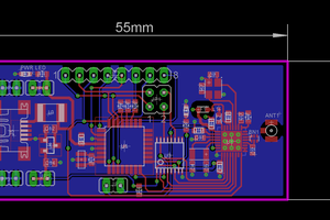
Intending to keep this as compact as possible I'm looking at BGA packages for SRAM and std package for the SPI Flash.  The several that I've chosen will enable me to keep costs below $30 for the whole board (target = $25) and still have head room to do some really impressive stuff with it.  Likewise, this makes a sizeable "prototype area" available to fill with either additional connectors or PTH pads.

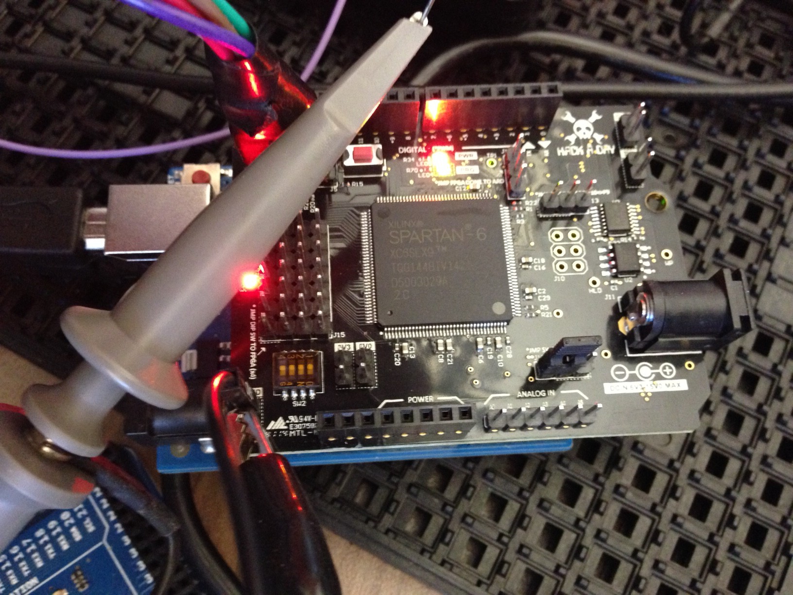
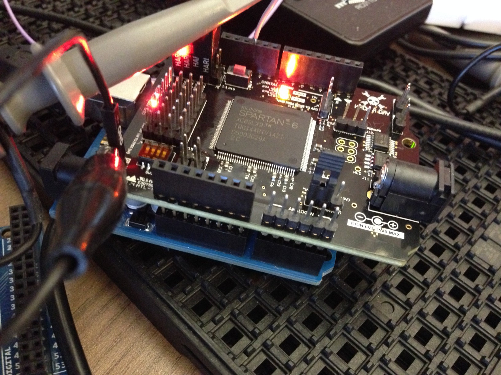
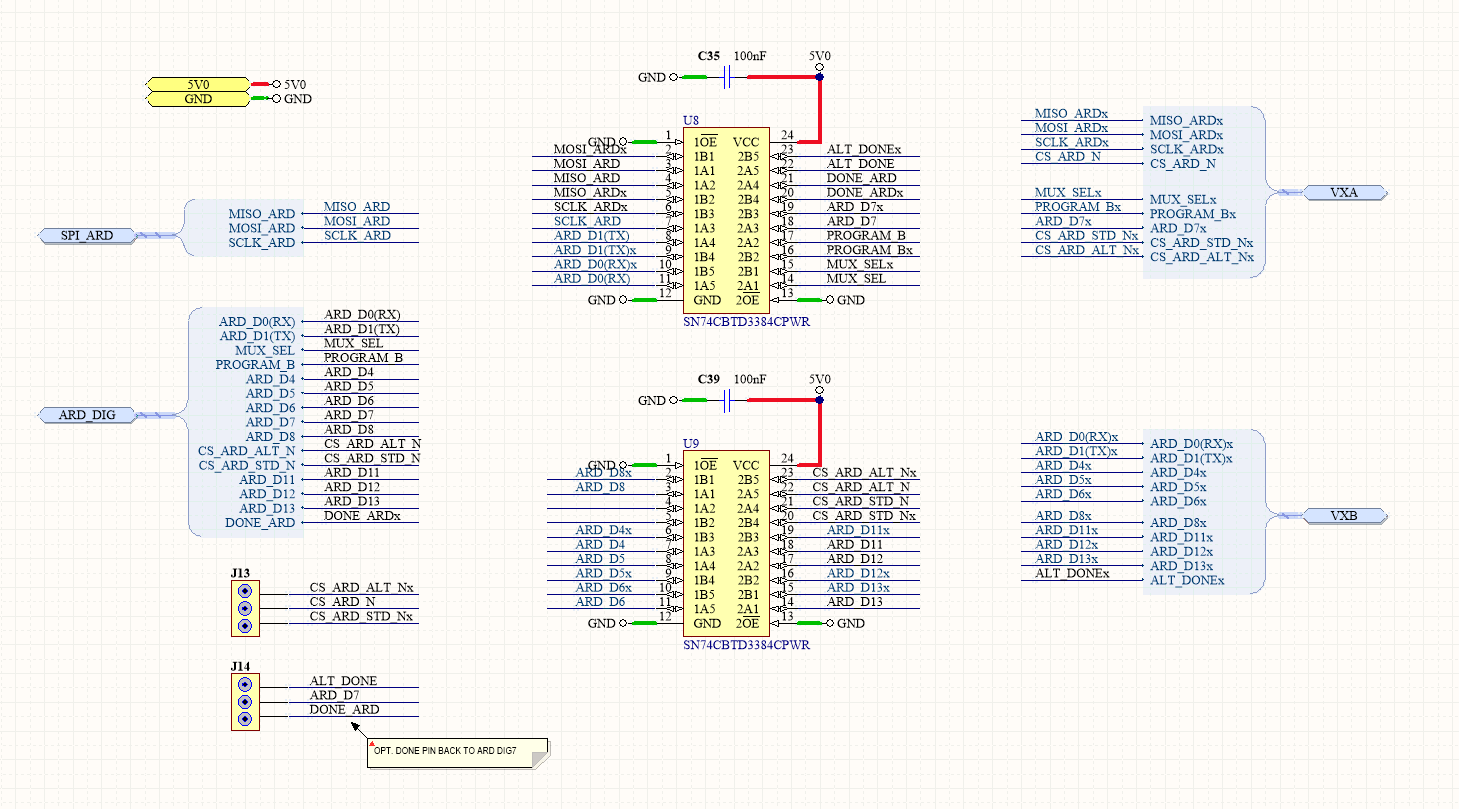
Programming of the SPI flash from Arduino is done via the ICSP header which carries thru to the "daughter" card.  Likewise, I've included a second chipselect (GPIO) to enable the ICSP to connect to the FPGA via SPI (were you to use an SPI slave core in the FPGA to drive FPGA functions...more on this in my next project ;)

Flash is meant to be large enough to be used by an FPGA processor in case someone wanted to use one, and also hold multiple images of the FPGA configuration if someone intends to make this harder to "brick".

Power is still undefined but relatively trivial.  Power supply will offer a few different rails and LEDs and line drivers will be used to provide some visual feedback of programming state and activity.

Git project -- https://github.com/sfgit/FPGA_Arduino_Shield.git

  • 1 × XC6SLX9-2TQG144C Xilinx Spartan 6 LX9 FPGA - Device Playground
  • 1 × S25FL216K0PMFI041 Spansion 16K flash - to hold FPGA configuration
  • 1 × SN74CBTLV3257DBQR SPI Multiplexer - manages access to flash from multiple SPI sources
  • 1 × KC5032A20.0000CM0E00 Kyocera 20MHz CMOS Oscillator - FPGA clock source
  • 1 × IS61WV12816DBLL-10BLI ISSI SRAM - 128Kx16 Asynchronous

  • Uploaded new files to Github

    technolomaniac07/09/2015 at 06:32 0 comments

    Made a few minor cosmetic tweaks, did some stuff on the PCB to try and make the next pass easier to add more IO (something that's been asked for) and really dialed in the output generators and outputs directory. Overall a nice cleanup prior to the latest round of fab. Boards are in the pipeline for mfg and will be 'in stock' very soon again! Check out the github repo. Also planning on changing the licensing to MIT so should make it much easier for folks interested in using this in their own products. Much of this can now be reused for my iCE40 design which is underway and after a 12-hour flight from SZ, I have only a little left to finish to make a second FPGA board, this time using the lattice parts. Altera to follow.

  • Uploaded first how-to video...Walkthru

    technolomaniac12/11/2014 at 07:10 1 comment

    Just uploaded my first video on actually using the board. There are a few others to follow. The video is found on Youtube:

    This describes the various interfaces, the use of the resources, the jumper settings, power supply, etc.

    I have also uploaded the first "Blinking LEDs" example for use with the Xilinx software, available on Github.

  • More FPGA Boards Back & Working!

    technolomaniac10/28/2014 at 23:27 3 comments

    Whew! Last round of mods were huge because as you come to find out quickly, anytime you add a level translator to a board - much less two & much less 10 channels each - you end up having to reroute most of the PCB layout. And as though that wasn't enough, I decided to make a bunch of other small updates and signaling fixes / improvements such that board (a) is now meaningfully different from board (b). <Shudders>

    Still, today the box of boards came back - first time populated by someone other than me - and they look and (more importantly work) awesome. The board shop this time took their sweet time but the wait was worth the cost (almost 10:1 versus US companies for the same quote).

    A few more small tests and it's away they go to the store to be sold! :)

  • Level Translation Mods

    technolomaniac10/01/2014 at 23:57 0 comments

    The first pass of this board was built with the Due in mind (3V3) and other development boards that I had sitting around, almost all of which *other* than Arduino were 3.3V.   In planning the evolution of this however, it quickly made sense to include support for other 5V devices such as the Uno and other Arduino boards.  So I have gone ahead and added a Level Translation circuit and respun the board now with some level translators that will convert the Arduino's 5V0 outputs to a nice, user-friendly 3V3 signal for the FPGA.  This'll ensure support for the Uno and other Arduino's not using 3V3 IO voltages.  Likewise, I made a few other small improvements and fixed a few snags that deserved some attention.  

    Testing the level translator on a breadboard...

    Schematic for the level translation circuit...

    Above is the schematic (new files will be uploaded to github shortly) for the level translator and because the layout needed to change pretty substantially to accommodate these two new devices, the boards went back to fab and are going thru proper assembly at the moment.  

    The part used for level translation is the SN74CBTD3384.  It's a 24-pin TSSOP and it's relatively small, cheap, and performs pretty well with very low series resistance.  Designed for performance up to about 10 MHz and provides  a nice interface to the arduino UNO and other 5V0 devices.  

  • Glamour shots

    technolomaniac09/04/2014 at 00:33 1 comment

    Nothing really to add here except a few simple glamour shots to show how things ended up.  Connected, in this case, to a Due just for fun.  

  • building a (budget) box I'd be happy to open

    technolomaniac08/24/2014 at 20:47 0 comments

    Recently I'd gotten a fair bit of interest from folks wanting to buy or or trade for one of these FPGA boards...And I must admit, I'm not terribly capitalistic when it comes to stuff I build outside of the work context (I often find I just end up giving stuff away, rather than trying to profit on them).  Still, I feel that generally everything I build is a reflection / measure of me and my interests and passions and enthusiasm and as a result, I hate to "ship" junk.  And I hate to own junk!  Better put: I want things to look pro, even if they're outside of the professional context (things move slower, but they just tend to be more 'agreeable' all-round).   

    So when it came time to come up with boxes to ship to folks, I thought I'd spend a little time trying to get this right.  And though I began by getting it wrong - all wrong - I managed to recover nicely I think and these express the 'spirit' of this board in a way that makes me comfortable sending it to my mates / others I've come to know thru electronics / n'er-do-well hackers, what-not.

    So the first order of boxes arrived an candidly, they sucked.  Corrugated die cut, white on one side, natural on the other.  The white is faded, poorly applied, the folds are not crisp and clean, the slots look to have been cut far to large for the flap thickness (makes the boxes loose along the edges) and the overall accuracy is rubbish.  I'm embarrassed for the USA stamp they bothered to apply to a crap box.   You can see the thin paper over the corrugation making them weak and hard to managed without some serious tape / glue.  Have a look:

    *****

    **Still, I tried to "make-do" (if I find myself using this expression, it is undoubtedly a reflection of frustration and poor judgement more than anything else)

    ***

    ***Ok, complete rubbish.  I will NOT send this off to a friend.  It's totally unacceptable (I'm that guy that puts stickers in a box along with your xmas present...details!).  So I packed it in and I pinged my good friends at Uline.  They are pro.  They do boxes.  All sorts of boxes.  And they do them well.  

    What I got was a far superior product.  Well cut, sturdy,  and although slightly larger (4x4" vs 3x3") there is clearly a far better process afoot here than at the first place I used.  Still die cut but looks to been done with better materials, better equipment, and the sort of love I like to see. Have a look:

    ***

    ***Now that I had a better box, I still didn't have an awesome one.  I had something nice, solid, more precise, but I wanted awesomeness.  Maybe not apple's barely-air-gets-through precision (impossible to do in my house on a budget) but something that at least looked cool and that I might keep after I took the board out and use for knickknacks like jumpers or those extra header bits or such.  Nice to pack away that arduino or flying leads and have some room for the USB cable and what-not.  

    So I go my thinking cap on and thought to use the Hackaday logo on the outside of the box.

    First I tried some die-cut stickers...

    ***

    ***

    Nah, fail.  Nice and all, but too much contrast, not enough of a story in there.  

    This is a board for people who want to build whacky shit with FPGAs and it should reflect that.  I couldn't have a clean edge, precision cut sticker on the box.  (Inside maybe)  I needed something that also complemented the rough edges of the imperfect box.  So I just happened to be sitting in my office and inspired by a pic of graffiti that serves as my desktop background, I decided to use spraypaint.  

    (Think: sweet road crew awesomness...what better to have in your gearbag than an FPGA board?)  

    ...But with what image?  Why the Hackaday logo of course!  (thank you to the die cut sticker that served as my cheap stencil)

    ***

    Tag that thing...

    ***

    ***

    ***The lineup...

    ***

    ***Something I'd keep on my desk......

    Read more »

  • Ding ding...Round 2 - New board look purty

    technolomaniac07/17/2014 at 17:50 0 comments

    Got the new boards back from Advanced Circuits (they rock BTW...attention to detail like few others) and they look awesome.  Went with black soldermask this time around and it makes things look so much cooler (much more Hackaday-chic).  These boards have a few new details including dipswitches (bloody small!), LEDs, a few extra test points, tented vias (BGA Soldering loves tented vias!) and a few other cosmetic tweaks esp. to the silkscreen.  The first batch worked fine so hoping this works without issue as well.  

  • Parts arrive for first 50p run!

    technolomaniac07/16/2014 at 17:15 0 comments

    Got enough parts to build 50 boards today.  Updated stencils arrived, woo hoo!  Retreating into soldering dungeon to spin up one or two to verify all's well with the world.  

  • Board goes 3D - like *really* 3D

    technolomaniac07/15/2014 at 22:40 0 comments

    Added step models to all of the interesting parts of the board to make things look and feel more authentic and to size up enclosures and such that I will release that you can easily 3D print.  Have a look at the pic below in the project overview.

  • New Design Files Uploaded To Git

    technolomaniac07/04/2014 at 07:57 0 comments

    Uploaded a new batch of design files including PDFs to github.  The repository can be found here and this rev contains some nice functional improvements.  See previous project log for some details and see git log for summary of changes.  This will be the final few changes before I build a reasonable qty of these boards (~100).  If anyone's keen to own one, let me know...I have the BOM down pretty low now and be a nice addition to the tool chest.  

View all 35 project logs

  • 1
    Step 1

    Step 1 - Don't panic.

  • 2
    Step 2

    Step 2 - Import the Arduino board file into Altium Designer:  Using Altium Designer (AD) requires that I import Eagle board into AD.  AD14.x includes an Eagle importer.  Used source files from the Arduino site to import in AD.  

  • 3
    Step 3

    Step 3 - Build major footprints:  Costing the available board area requires building the major footprints and placing them on the PCB.  Built early footprints and placed to determine what additional space is avail.  Files in git.

View all 11 instructions

Enjoy this project?

Share

Discussions

Tommy wrote 09/16/2019 at 08:31 point

I also would like to buy this board. Spartan + SRAM + Arduino is exactly what I want. Is available anywhere?

  Are you sure? yes | no

jankuehn wrote 04/11/2018 at 11:52 point

Is the board still available somewhere or is there a follow-up project? I'd love to have one of these!

  Are you sure? yes | no

EngineerAllen wrote 02/03/2017 at 16:26 point

thanks

  Are you sure? yes | no

Vijayenthiran Subramaniam wrote 10/25/2016 at 12:57 point

Nice Project. I am beginner in FPGA. If I have a bit file generated from the Xilinx IDE, Can I use it to program this board via ICSP / JTAG programmer?

  Are you sure? yes | no

wujingbang wrote 03/24/2016 at 03:57 point

Finally, I've figured it out about the spi flash booting problem. It seems like that "MOSI_FPGA" is wrongly connected to the "CMPMOSI" pin of the FPGA, instead of the "MOSI_CSI_B_MISO" pin, which is the right pin to send the read cmd and address to the spi flash when the FPGA is reset. 

As a temporary solution, you can directly connect the "ARD_D6" pin to the SI pin of the spi flash. 

  Are you sure? yes | no

Pingasman wrote 12/22/2015 at 11:14 point

Hi there. I bought this board last month and now I'm trying to put a simple blinking leds example in it. Typically, I use a .ucf file in order to assign the FPGA pins to their internal signals according to the board datasheet. However, I don't find the information stating which FPGA pins are connected to the leds, or other I/O board pins, thus, I do not know how to drive my FPGA circuit to the outside world.
Is there any table converting which FPGA pins correspond to which board pins? Or at least can anyone tell me which pins are connected to the leds?

  Are you sure? yes | no

Nolan Moore wrote 11/24/2015 at 07:52 point

I picked up a board from the HaD store quite some time ago, and last night I finally found some time to begin really playing with the board. Unfortunately, the board came with no Arduino headers, and I spent a good bit of time trying to determine how to connect it to an Arduino. I ended up soldering a 2x3 to the ICSP slot. Good, next step!

I've had very little experience with FPGAs previously, but I realized that for this board I needed an Arduino that could flash SPI chips. I found no sketch nor tutorial here but flashed frser-duino to a Duemilanove. I've got it running with flashrom, and after pulling the MUX_SEL Arduino header pin high (flashrom couldn't see the SPI chip otherwise) I can access the chip. I'd seen the bit file in the HelloWorld example mentioned and attempted to write it, but the size was incompatible (wrong file I assume). 

I'll try following along with the tutorials presented for the Mojo dev board next (up until I get the file to flash) as it seems to use the same Xilinx chip, but I just wonder if there was a tutorial I missed somewhere or a sketch I could have used. Also, since was needing to pull MUX_SEL high was never mentioned, is that an indicator that something's wrong with my board? Thanks!

  Are you sure? yes | no

wujingbang wrote 03/20/2016 at 03:06 point

Hi, I've been stuck in the issue "what file to flash into the spi flash" for a while. I've tried the bit file, or the bin file generated by the promgen, but nothing works.. Could you give me some advises? Thanks! 

  Are you sure? yes | no

Doan Trung Nghia wrote 09/22/2015 at 07:19 point

I've bought this board few days ago, the thing makes me confused is about voltage shifters. They are all removed ? It means that I cant directly connect this board to my Arduino UNO, which is 5V tolerant ? Could anybody please confirm it ? Thank you guys so much. 

  Are you sure? yes | no

technolomaniac wrote 09/22/2015 at 07:25 point

When did you buy it?

  Are you sure? yes | no

Doan Trung Nghia wrote 09/22/2015 at 07:27 point

Hi, my professor brought many boards to our lab and we are investigating about this board.  It can be last week. 

  Are you sure? yes | no

ben biles wrote 08/01/2015 at 02:34 point

hi, I was'nt clear if the level shifters can translate 3.3v and 5v from either arduino Uno and arduino Due ? I'm not sure if my project will need to use the UNO or DUE yet. how much power (ma) does the fpga draw ? or is that down to how much of the FPGA you program and what its doing? lastly, are there female headers on the borad to add another shield? in one video it looked like male headers on top? I have a USBhost shield I want to run with your FPGA shield, do you think they will work together? I'm new to fpga but hope to do some RF things, perhaps code a PLL and try to recieve radio etc.. 

  Are you sure? yes | no

Antti Lukats wrote 08/01/2015 at 09:49 point

all modern FPGAs have max IO voltage tolerance of 3.3V (without level shifters). Level shifter OTOH are major PITA. Really they are, bidirectional level shifters destroy signal quality and in worst case even oscillate!

Digital PLL can be "coded" yes but that not sufficient for real radio receiver.

  Are you sure? yes | no

ben biles wrote 08/01/2015 at 11:26 point

ah, so is the fpga shield is arduino due compatible or not? I think DUE is 3.3v logic IO, I agree level shifters are a pain,  I just tried to use them between a a codec and arduino UNO  and it just would not work.. The logic voltage level was supposed to be 1.8v not 3.3v on the i2c and I used the correct i2c capable level translator.. Errrr frustrating... Deforming the slew rate or something probebly... I don't have an oscilloscope yet so hard to know.. Regarding fpga,  if not pll then perhaps I can do some decimation or premodulation techniques to reduce bandwidth for my digital audio 8fsk transmission.. I'm experimenting with a TI pll synthesizer / modulator chip but need to reduce bandwidth from ADC in as lowest possible latency possible.. Maybe I should be looking at DSP for this though.. Not sure yet..  Maybe fpga isn't the way to go for low latency wireless digital audio in sub 1ghz rf.. Mmm early days... 

  Are you sure? yes | no

Sercan Aygün wrote 07/27/2015 at 14:09 point

Dear technolomaniac,
For my thesis, I have a deep interest to use Arduino compatible FPGA shield as you illustrate. I have a card UDOO which has Arduino Due itself as an extra speciality. But I wonder if this FPGA shield is fully compatible with Arduino Due or not. As I can see you use Due but maybe you should share the details. If you could help me, I would be very glad.

Best Regards.

  Are you sure? yes | no

midnitesnake ☯ wrote 05/22/2015 at 18:31 point

Is Lucid (https://www.sparkfun.com/news/1837) compatible with this board?

  Are you sure? yes | no

Serge.V wrote 05/21/2015 at 05:42 point

Wow, marvelous project! I believe it should be possible to program MIPSfpga into it and use it as a customized microcontroller board. http://linuxgizmos.com/imagination-to-release-open-mips-design-to-academia

  Are you sure? yes | no

Crypto [Neo] wrote 05/06/2015 at 12:14 point

This is a great project! I can see a lot of people being interested in buying something like this (us included!)

  Are you sure? yes | no

technolomaniac wrote 07/08/2015 at 17:47 point

So there are boards in the pipeline as I write this!  More on the way.  Just got a bunch ordered and made a few small updates on the the design (avail in the repo).  

  Are you sure? yes | no

flora.tao wrote 04/09/2015 at 08:00 point

Nice project!  This is flora from Seeedstudio , an hardware innovation platform based in China. We are very interested in your FPGA and wondering if we could feature your FPGA boards on our official website. If you are also interested in the market we strong with please get back to me : flora.tao@seeed.cc

  Are you sure? yes | no

counter.culture wrote 04/09/2015 at 08:49 point

Goto his github...he has open sourced it and "freed" it through GPL.  Read signal7's comments below about breaking out all the pins before starting your production - you should amend the design a bit.

  Are you sure? yes | no

technolomaniac wrote 04/10/2015 at 00:25 point

Wait!  I have a new version!  :)  I will upload to github soon but the version that is on there is now out of date.  The new version has a few things that have been modified to work much better.  It too will be open sourced!

  Are you sure? yes | no

counter.culture wrote 04/10/2015 at 00:52 point

very good

  Are you sure? yes | no

technolomaniac wrote 04/10/2015 at 00:26 point

Hi flora!  Happy to have your help.  You can private message me and I will share with you the details of the project.

  Are you sure? yes | no

Nicolas Siret wrote 03/20/2015 at 16:13 point

Great project Technolomaniac! Will you have more boards for sell in the coming weeks/months? We have developed a new language & an IDE to make easy and quick the design and verification of hardware (www.synflow.com) and I would like to propose this board to our users. 

  Are you sure? yes | no

technolomaniac wrote 07/08/2015 at 17:47 point

Boards in the pipeline now!  Sorry for the delay but there are a bunch going thru the system as we speak!

  Are you sure? yes | no

Stephan Mühlstrasser wrote 02/01/2015 at 21:41 point

I found this board because I'm interested in an FPGA board that can be combined with an Arduino. I'm searching for a platform for implementing an emulator of a floppy disk controller and the floppy drives themselves for an old 6502-based BASIC computer (Ohio Scientific Challenger 1P).

I have zero experience so far with FPGAs. Would it be feasible to implement such an emulator with this FPGA board?

  Are you sure? yes | no

ajcrm125 wrote 01/30/2015 at 01:11 point

Question... does the Arduino program the SPI Config Flash which in-turn, programs the FPGA? Or does the Arduino program the FPGA directly?

Thanks!

  Are you sure? yes | no

technolomaniac wrote 07/08/2015 at 17:49 point

Arduino can program the SPI flash then controls the boot sequence on the FPGA to cause it to load its config from flash.  This'll make the whole thing programmable from the arduino so long as it has a bit file.

  Are you sure? yes | no

midnitesnake wrote 01/18/2015 at 10:28 point

Is it possible for you to post a quick beginners tutorial on programming the device. I bought this board to practise and learn FPGA programming; so I am new in this area. I've been having a hard time working out Xilinx s/w. I found the ISE version you need is 13.6 as opposed to the later Vivaldo versions; following another online example I've generated some blink-led code. But can't progress any further - I'm now stuck on the Impact design?

I think FPGA beginners (like me) need a simple walkthrough from loading code, compiling, and programming the device. Thanks in advance.

  Are you sure? yes | no

signal7 wrote 01/12/2015 at 18:34 point

So - one problem I see here is that not all of the IOs are brought out to a connector. All of bank 3 is soldered to the board, but it looks as though there are no traces. While I certainly *could* deadbug solder to those pins with some wirewrap wire, I'd really rather not fill the swear jar in a single afternoon. The problem is I need 52 IO lines and there's 24 of them that seem to go nowhere.

Is it possible to do a board with all of the connections brought out to a header? I might take a stab at changing your board, but I'm really not sure I have the capability to solder all of the parts. Any BGAs are pretty much beyond my equipment capability at the moment. Otherwise it looks perfect.

  Are you sure? yes | no

Daniel Wisehart wrote 01/09/2015 at 02:56 point

Nice board. I just ordered two.

Any thoughts on what will plug into the FPGA I/O pins? (besides flying headers.) It would be nice if this Arduino prototyping board would just plug in, but that is probably asking too much I am thinking: https://www.sparkfun.com/products/7914

I guess I can take your board file and create a two-layer board similar to the prototype board I linked to. Anyone else interested in buying something a plug-in prototyping board if I had several made?

  Are you sure? yes | no

technolomaniac wrote 01/12/2015 at 23:27 point

I'd be keen and if you want some help in dreaming up plug-in boards, I'm game! :) I have a few in mind for when I get some time but time is pretty tight atm. [

  Are you sure? yes | no

Similar Projects

Does this project spark your interest?

Become a member to follow this project and never miss any updates