 Spencer Maroukis
Improvements before next batch:
Kit-friendly improvements
- replace resistor arrays with 0805 discretes;
- MCU + firmware → Arduino IDE compatible
Other improvements
- Change the CC orientation LED design to: (A side) STD [FLIP] (B side) STD [FLIP] (still 4 LEDs but now 2 indicators at a time)
- Low power mode / power time off to save battery - Remove DIP switch for cost
- add OSHW logo and nec. files
- A diagnose for the Shield connection (see comments)
---
See the repo for an in depth description of operation, footprints, gerbers, and firmware and this blog post for my thoughts on working with JLCPCB and KiCad and other lessons learned.
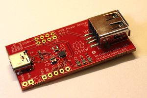
The project is a hardware fork of aroerina/LimePulse that I decided to reverse engineer and write the firmware for to get experience with KiCad and STM32 development.
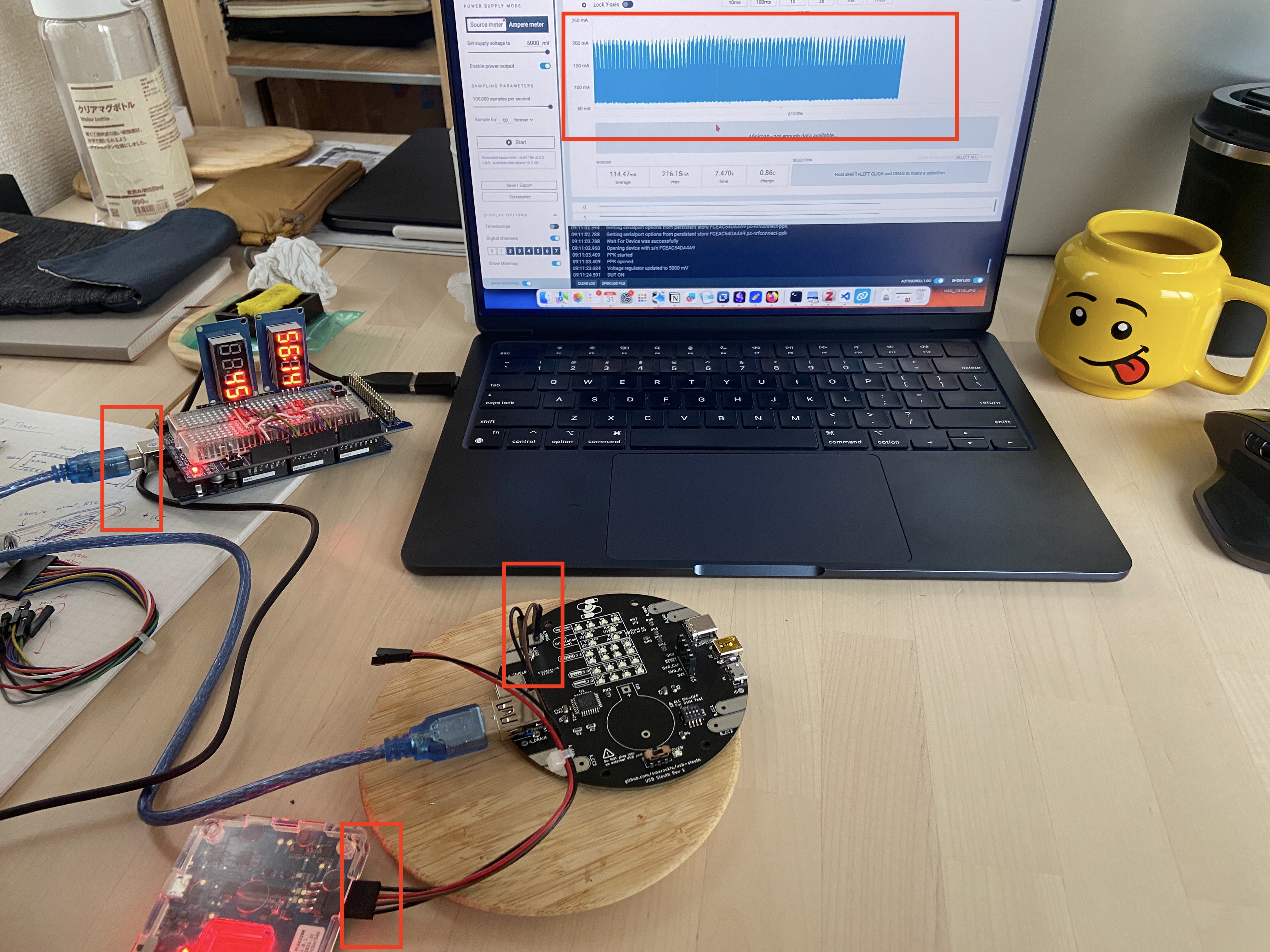
A STM32C031K6T microcontroller is used for testing connection and orientation, powered by a CR2032 battery. Code is given using STM32 HAL libraries and the device can being programmed over SWD.
KiCad and gerber files are provided for the board layout, as well as the library footprints for non-standard parts ordered from JLCPCB/LCSC.
This USB cable tester has the "B" side on the right, and the "A" side on the left. Receptacles are given for the following:
- Type-C (both sides)
- Type-C to A
- Type-C to micro B (2.0)
- Type-C to mini B

DMM Test of Internal Resistor
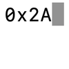
Testing the value of the pulldown resistor on an active cable by measuring between B_CC2 and B_GND (should be between 800-1.2K Ohms).

Attributions
Icons
- Fedora Hat by Sanjib Biswas from vecteezy - Silhouette PNGs by Vecteezy
- tip by Hothouse Design from Noun Project (CC BY 3.0)
- Warning by Deylotus Creative Design from Noun Project (CC BY 3.0)
Inspired By
- https://github.com/petl/USB-C-cable-tester-C2C-caberQU
- https://github.com/alvarop/usb_c_cable_tester
- https://github.com/aroerina/LimePulse_USB_cable_checker/ - original inspiration for the design and functionality from its professional quality layout
Thanks
s/o to Tokyo Hackerspace where you can find more people working on projects like this on Tuesdays.


 jason Cerundolo
 mulcmu
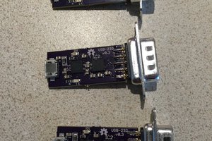
 Nick Sayer
I am very interested to order a board.